 |
| FlashWebHost.com | Resources | Ham Radio Circuits | Ham Radio | SSB Transceiver | |
According to the radio regulations in most countries, any licenced radio amateur must have a non-radiating load to connect to his transmitter's RF output. The use of such a load is mandatory for off-air adjustment of the transmitter.
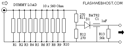
The load described here is capable of handling up to 10 watts of RF power for a couple of minutes, and is designed for the widely used 50 ohms impedance. It consists of ten parallel connected 560 ohms 1 watt resistors, R1 through R10, a voltage divider, R11-R12, and a rectifier D1-C1. Apart from loading the transmitter output with a minimum of reflected power, the dummy load also provides a direct voltage output to which a voltmeter may be connected to measure the RF power. If the dummy load is used for power levels higher than 10 watts simply use more, or higher wattage resistors to give a total of about 50 ohms. For instance, by using twenty 2 watt 1,200 ohms resistors instead of R1-R10 and 150 ohms resistors for R11 and R12, the dummy load is turned into a 40 watt version. The diode may be almost any Schottky type. Types like BAT85 and HSCH1001, for instance, are also suitable. Even a germanium type like the AA119 will work, but then for low powers only.
The dummy load is housed in a tin can of which the cover is used to mount the components. As illustrated, the ten 560 ohms resistors are soldered in a circlearound the center pin of the BNC socket. Their ground terminals are soldered flush to the inside of the cover. Capacitor C1 is a feed through type for which a small hole must be drilled in the cover. All resistors should be mounted with the shortest possible lead lengths to keep the reactive component of the dummy load as small as possible. After mounting the parts, the cover is fitted on to the tin can again, and soldered all around to seal the dummy load completely. Do not drill ventilation holes in the tin can because that will defeat the purpose of making a non-radiating load. The can may get quite hot when transmitter power is applied for a while, but that is no cause for concern.
The voltmeter read-out produced by the dummy load may be calibrated against a professional RF voltmeter (for instance a 'real' Bird Thruline). The voltages obtained at differebt RF power levels are noted so that a graph can be made. Depending on the reactive characteristics of the resistors used, the dummy load should exhibit a VSWR of less than 1.5 for frequencies up to 450 MHz. Resistors R13 may be omitted if the dummy load is always used with same voltmeter.

| Website designed by FlashWebHost.com. All rights reserved. |